Draw Vetical Crest Curve Given Slopes in Autocad
VGE - Vertical Grading Editor
Introduction
TheVertical Grading Editor is the central design feature of Advanced Road Design . It provides for the full vertical grading (profile) design and cross section generation of multiple roads, strings, kerb returns, cul-de-sacs, knuckles, and other ARD object types.
The Vertical Grading Editor is accessible:
- At the time of creating
- Roads
- Strings
- Kerb Returns
- Cul-de-sacs
- Knuckles
- For editing an existing ARD Object (Road, String, Kerb Return, Cul-de-sac, Knuckle, Roundabout or Off Ramp)
Civil 3D Interactions
All profile adjustments made in the Vertical Grading Editor can be passed back to the Civil 3D profile by running the ![]() Create/Update Civil 3D Profiles command.
Create/Update Civil 3D Profiles command.
Profiles that are generated using the ![]() Create/Update Civil 3D Profiles can be edited in AutoCAD Civil 3D and the changes to the profiles can update the ARD Vertical Grading designs by running the
Create/Update Civil 3D Profiles can be edited in AutoCAD Civil 3D and the changes to the profiles can update the ARD Vertical Grading designs by running the ![]() Intersection Match-In command.
Intersection Match-In command.
Main Features and Benefits
This is an interactive and interconnected vertical grading (profile) design environment with the following features and benefits:
- a full set of vertical design tools to graphically and/or numerically create/edit IP's (PVI's) and vertical (parabolic) curves
- a range of tools to automatically create IP's and vertical curves based on existing or other design data.
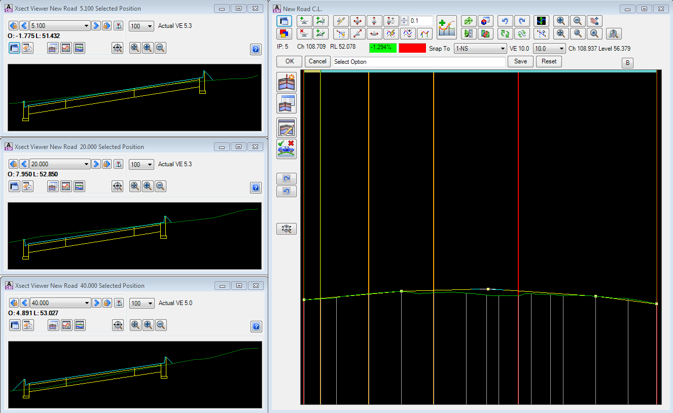
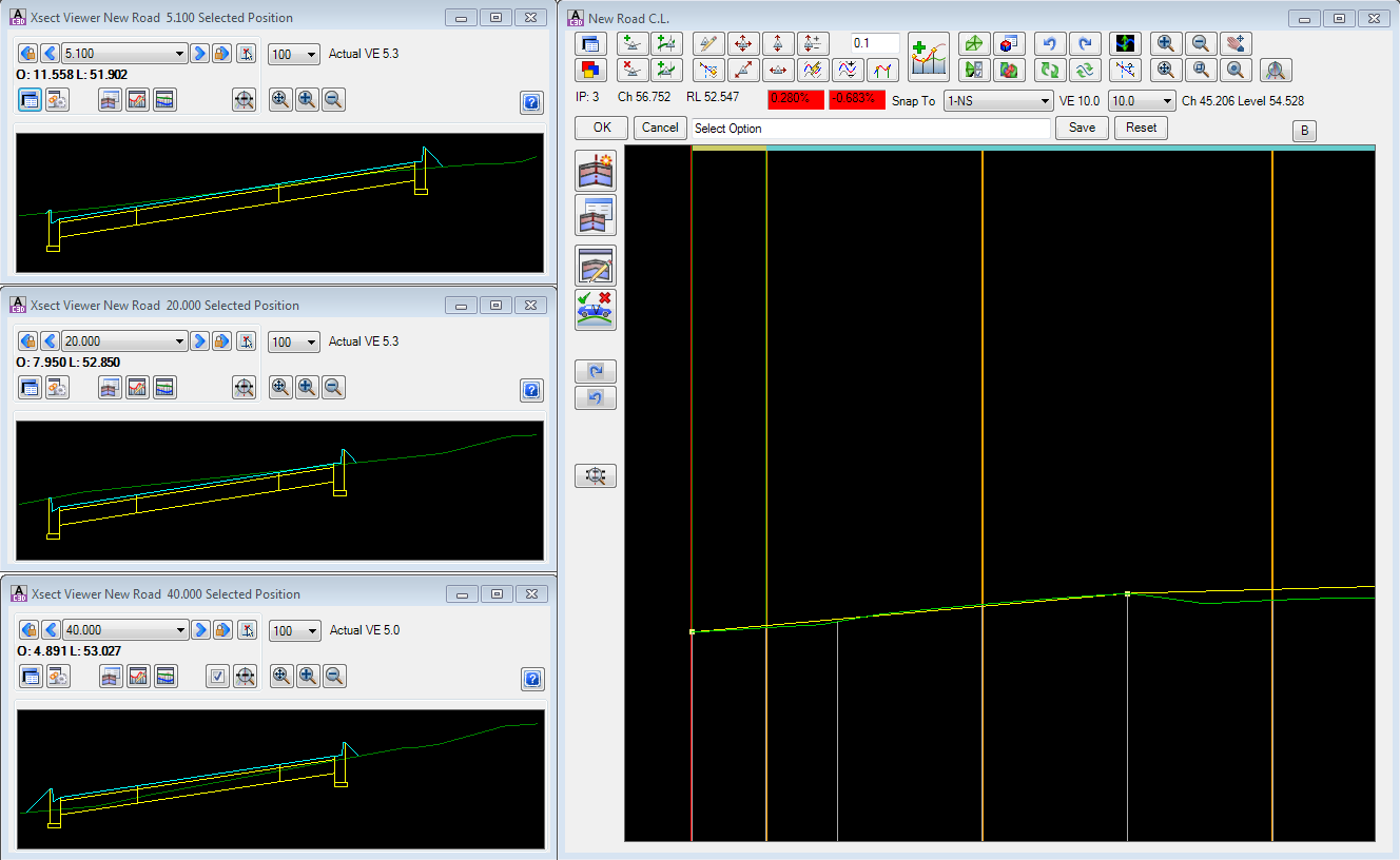
- the ability to open multiple Cross Section Windows from the vertical grading editor display
- direct access to the
 Create/Edit Templates form to facilitate creation/editing of cross section templates
 - the inclusion of a 'model space' tracker in the drawing window to co-ordinate the mouse position in the Vertical Grading Editor with the position in the model. The marker will automatically resize as you zoom in the drawing window.
- multiple Vertical Grading Editor windows can be opened and edited simultaneously, so designers can see the effect of changing a Vertical Grading on any other interconnected ARD Object (such as side/crossing roads, kerb returns and cul-de-sacs)
- the Vertical Grading Editor window is modeless - designers can simultaneously execute commands and work in the AutoCAD Civil 3D environment
- the Vertical Grading Editor window is fully re-scalable - the vertical grading (profile) exaggeration and width will automatically adjust to accommodate the space of the window
- crossing Road strings are shown on the vertical grading editor window and includes the name of the crossing road string
Marker/Tracker Display in the Drawing
The display of the 'tracker' that shows the relative location of the marker in the drawing is managed via a block in the Advanced Road Design Settings (ARD Settings) folder. Users are able to replace this drawing block as desired. The ARD Settings folder can be opened in Windows Explorer via the Open Settings Folder command in the General menu/ribbon. The block is named VGEMarker.dwg.
Details
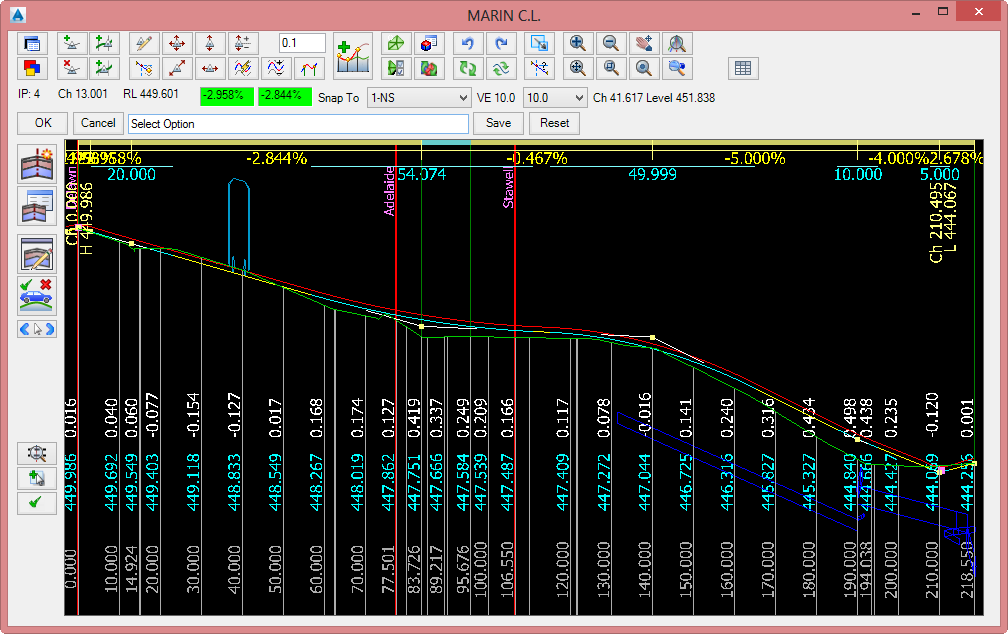
The Vertical Grading Editor provides multiple Vertical Grading Design windows to edit the design long sections (profiles) of any number of Roads, Strings/Profiles, Kerb Returns, Cul-de-sacs, Knuckles , Roundabouts and Off Ramps simultaneously, whilst still maintaining interactivity between dependent components (eg: Side road vertical gradings match the cross section of the Main Road roadway at the intersections. Kerb returns, Cul-de-sacs and Knuckles automatically match the edge of the road for the Main Road and Side Road at their start and end).
Upon opening the Vertical Grading Editor the following form is displayed:
| Details of the form are as follows: | ||||||||||||||||||||||||||||||||||||||||||||||||||||||||||||||||||||||||||||||||||||||||||||||||||||||||||||||||||||||||||||||||||||||||||||||||||||||||||||||||||||||||||||||||||||||||||||||||||||||||||||||||||||||||||||||||||||||||||||||||||||||||||||||||||||||||||||||||||||
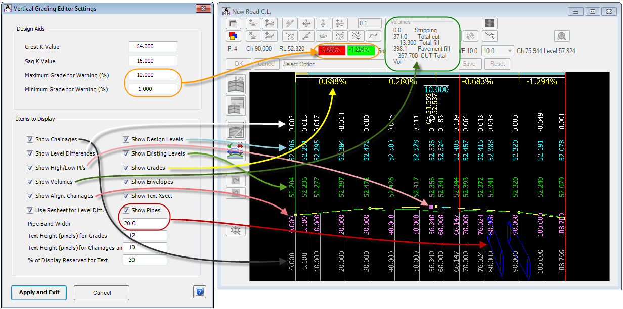
| | | The display of profile grades, high/low points, level information and text size can be controlled by the designer. This is achieved by clicking on the Note: These controls are mirrored in the The controls of the form are graphically outlined below:
| ||||||||||||||||||||||||||||||||||||||||||||||||||||||||||||||||||||||||||||||||||||||||||||||||||||||||||||||||||||||||||||||||||||||||||||||||||||||||||||||||||||||||||||||||||||||||||||||||||||||||||||||||||||||||||||||||||||||||||||||||||||||||||||||||||||||||||||||||||
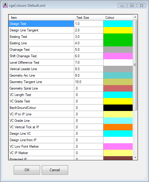
| | | This command allows the designer to customise the display of the Vertical Grading Editor (VGE). Here, the designer can edit the size of text displayed and assign colours to text and other items, such as the VGE background colour. The Set Vertical Grading Editor Window Colours command has further information on this form. | ||||||||||||||||||||||||||||||||||||||||||||||||||||||||||||||||||||||||||||||||||||||||||||||||||||||||||||||||||||||||||||||||||||||||||||||||||||||||||||||||||||||||||||||||||||||||||||||||||||||||||||||||||||||||||||||||||||||||||||||||||||||||||||||||||||||||||||||||||
| IP Create/Delete Tools | This collection of commands enable creation and deletion of IPs | |||||||||||||||||||||||||||||||||||||||||||||||||||||||||||||||||||||||||||||||||||||||||||||||||||||||||||||||||||||||||||||||||||||||||||||||||||||||||||||||||||||||||||||||||||||||||||||||||||||||||||||||||||||||||||||||||||||||||||||||||||||||||||||||||||||||||||||||||||
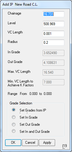
| | | Adds an IP (PVI) to the Design Vertical Grading (Long Section/Profile). Upon starting the command the Vertical Grading Editor prompt will display Click to Insert New IP. Use the mouse pointer to graphically select a location in the Vertical Grading Design Window . The following form is displayed:
| ||||||||||||||||||||||||||||||||||||||||||||||||||||||||||||||||||||||||||||||||||||||||||||||||||||||||||||||||||||||||||||||||||||||||||||||||||||||||||||||||||||||||||||||||||||||||||||||||||||||||||||||||||||||||||||||||||||||||||||||||||||||||||||||||||||||||||||||||||
| | | Deletes an IP (PVI) from the Design Vertical Grading (Long Section/Profile). Upon starting the command the Vertical Grading Editor prompt will display Click on IP to Delete. Use the mouse pointer to graphically select an IP in the Vertical Grading Design Window . The selected IP will be deleted from the design. A new tangent will be created between the two adjoining IP's to form a continuous long section. | ||||||||||||||||||||||||||||||||||||||||||||||||||||||||||||||||||||||||||||||||||||||||||||||||||||||||||||||||||||||||||||||||||||||||||||||||||||||||||||||||||||||||||||||||||||||||||||||||||||||||||||||||||||||||||||||||||||||||||||||||||||||||||||||||||||||||||||||||||
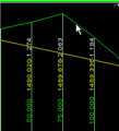
| | Creates an IP at a cross section nearest the selected location, with the level (elevation) being adopted from the surface or Design Constraint as shown in the Snap To field (by default, this is the sampled (existing) surface). Upon starting the command the Vertical Grading Editor prompt will display Select Point on <Snap To>. Use the mouse pointer to locate the nearest cross section where the IP is required. An IP will be created with levels applied based on the surface/constraint shown in the Snap To field, with a VC length of .001m. Example shown, below:
| |||||||||||||||||||||||||||||||||||||||||||||||||||||||||||||||||||||||||||||||||||||||||||||||||||||||||||||||||||||||||||||||||||||||||||||||||||||||||||||||||||||||||||||||||||||||||||||||||||||||||||||||||||||||||||||||||||||||||||||||||||||||||||||||||||||||||||||||||||
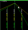
| | | Creates an IP with the chainage adopted from the location selected by the user and with the level (elevation) being adopted from the surface or Design Constraint as shown in the Snap To field (by default, this is the sampled (existing) surface). Upon starting the command the Vertical Grading Editor prompt will display Select Chainage on <Snap To>. Use the mouse pointer to locate the chainage where the IP is required. An IP will be created with levels applied based on the surface/constraint shown in the Snap To field, with a VC length of .001m. Example shown, below:
| ||||||||||||||||||||||||||||||||||||||||||||||||||||||||||||||||||||||||||||||||||||||||||||||||||||||||||||||||||||||||||||||||||||||||||||||||||||||||||||||||||||||||||||||||||||||||||||||||||||||||||||||||||||||||||||||||||||||||||||||||||||||||||||||||||||||||||||||||||
| IP Editing Tools | This collection of commands provide graphical and numerical editing of the IP's | |||||||||||||||||||||||||||||||||||||||||||||||||||||||||||||||||||||||||||||||||||||||||||||||||||||||||||||||||||||||||||||||||||||||||||||||||||||||||||||||||||||||||||||||||||||||||||||||||||||||||||||||||||||||||||||||||||||||||||||||||||||||||||||||||||||||||||||||||||
| | Numerically edit an IP by selecting it in the drawing. Upon starting the command the Vertical Grading Editor prompt will display Select IP to Edit. Use the mouse pointer to graphically select an IP in the Vertical Grading Design Window . Note: Except for the title of the form, the design inputs exactly match the | |||||||||||||||||||||||||||||||||||||||||||||||||||||||||||||||||||||||||||||||||||||||||||||||||||||||||||||||||||||||||||||||||||||||||||||||||||||||||||||||||||||||||||||||||||||||||||||||||||||||||||||||||||||||||||||||||||||||||||||||||||||||||||||||||||||||||||||||||||
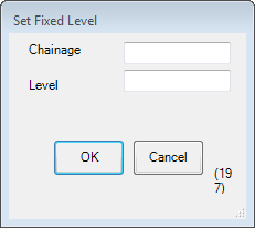
| | Edit an IP by setting a Chainage and Level that the design vertical grading must intersect. The selected IP will be raised/lowered so that the design vertical grading passes through the specified chainage and level. Upon starting the command the Vertical Grading Editor prompt will display Select Required IP. After selecting the IP to edit the following form is displayed:
| |||||||||||||||||||||||||||||||||||||||||||||||||||||||||||||||||||||||||||||||||||||||||||||||||||||||||||||||||||||||||||||||||||||||||||||||||||||||||||||||||||||||||||||||||||||||||||||||||||||||||||||||||||||||||||||||||||||||||||||||||||||||||||||||||||||||||||||||||||
| | | Graphically move an IP anywhere within the limits of the constraining vertical curves or other IPs. Upon starting the command the Vertical Grading Editor prompt will display Click on IP to Move. Click on or near an IP to select it for relocation. After selecting an IP it can be moved using the mouse. Click to store the new IP location. | ||||||||||||||||||||||||||||||||||||||||||||||||||||||||||||||||||||||||||||||||||||||||||||||||||||||||||||||||||||||||||||||||||||||||||||||||||||||||||||||||||||||||||||||||||||||||||||||||||||||||||||||||||||||||||||||||||||||||||||||||||||||||||||||||||||||||||||||||||
| | | Graphically slide an IP along an incoming or outgoing grade. Upon starting the command the Vertical Grading Editor prompt will display Click on IP to Slide. Click immediately to the left of an IP to hold the grade left of the IP. Click immediately to the right of an IP to hold the grade right of the IP. Use the mouse to set the new position of the IP. Click to store the new IP location. | ||||||||||||||||||||||||||||||||||||||||||||||||||||||||||||||||||||||||||||||||||||||||||||||||||||||||||||||||||||||||||||||||||||||||||||||||||||||||||||||||||||||||||||||||||||||||||||||||||||||||||||||||||||||||||||||||||||||||||||||||||||||||||||||||||||||||||||||||||
| | | Graphically move an IP up or down whilst constraining movement along the chainage. Upon starting the command the Vertical Grading Editor prompt will display Click on IP to Move. Click on or near an IP to select it for relocation. After selecting an IP it can be moved using the mouse. Click to store the new IP location. | ||||||||||||||||||||||||||||||||||||||||||||||||||||||||||||||||||||||||||||||||||||||||||||||||||||||||||||||||||||||||||||||||||||||||||||||||||||||||||||||||||||||||||||||||||||||||||||||||||||||||||||||||||||||||||||||||||||||||||||||||||||||||||||||||||||||||||||||||||
| | | Graphically move a selected IP left/right and constrain any vertical movement. Upon starting the command the Vertical Grading Editor prompt will display Click on IP to Move Left/Right. Click on or near an IP to select it and use the mouse to drag the IP left or right to set the new position of the IP. Click to store the new IP location. | ||||||||||||||||||||||||||||||||||||||||||||||||||||||||||||||||||||||||||||||||||||||||||||||||||||||||||||||||||||||||||||||||||||||||||||||||||||||||||||||||||||||||||||||||||||||||||||||||||||||||||||||||||||||||||||||||||||||||||||||||||||||||||||||||||||||||||||||||||
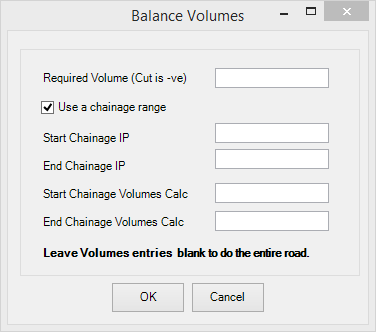
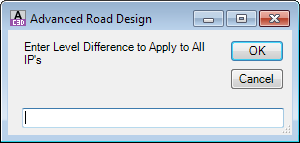
| | | Move an IP up and down by a user defined increment. Upon starting the command the Vertical Grading Editor prompt will display Select IP to Raise/Lower. After selecting the IP the prompt changes to Use Up/Down. Select Drawing to End and a scroll icon As indicated by the prompt, stop the command by clicking the left mouse button in the graphics area. Special Note: If the option 'Show Volumes' is toggled on in the | ||||||||||||||||||||||||||||||||||||||||||||||||||||||||||||||||||||||||||||||||||||||||||||||||||||||||||||||||||||||||||||||||||||||||||||||||||||||||||||||||||||||||||||||||||||||||||||||||||||||||||||||||||||||||||||||||||||||||||||||||||||||||||||||||||||||||||||||||||
| | |
| ||||||||||||||||||||||||||||||||||||||||||||||||||||||||||||||||||||||||||||||||||||||||||||||||||||||||||||||||||||||||||||||||||||||||||||||||||||||||||||||||||||||||||||||||||||||||||||||||||||||||||||||||||||||||||||||||||||||||||||||||||||||||||||||||||||||||||||||||||
| | |
| ||||||||||||||||||||||||||||||||||||||||||||||||||||||||||||||||||||||||||||||||||||||||||||||||||||||||||||||||||||||||||||||||||||||||||||||||||||||||||||||||||||||||||||||||||||||||||||||||||||||||||||||||||||||||||||||||||||||||||||||||||||||||||||||||||||||||||||||||||
| | | This command is used to insert a either a single vertical curve or a vertical curve pair based on the incoming grade to the first IP and the outgoing grade from the second IP. The process is the same as is used for designing Kerb Returns and is as follows:
| ||||||||||||||||||||||||||||||||||||||||||||||||||||||||||||||||||||||||||||||||||||||||||||||||||||||||||||||||||||||||||||||||||||||||||||||||||||||||||||||||||||||||||||||||||||||||||||||||||||||||||||||||||||||||||||||||||||||||||||||||||||||||||||||||||||||||||||||||||
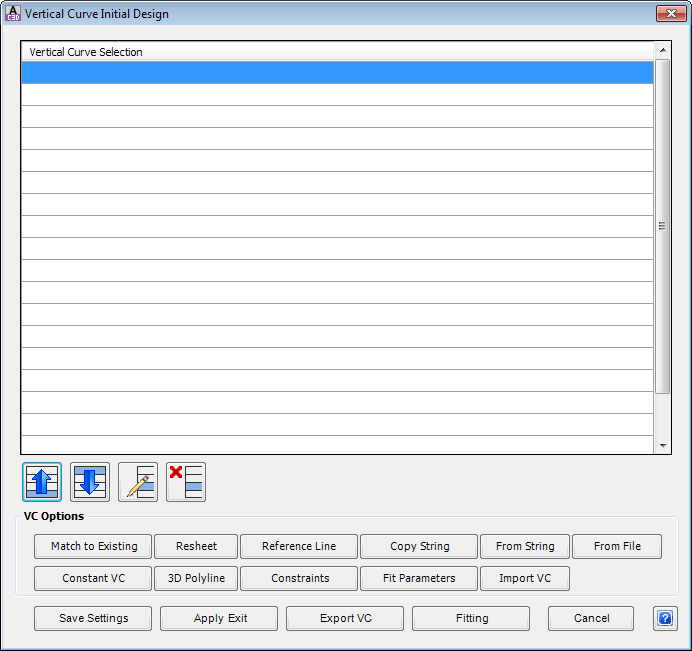
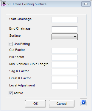
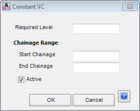
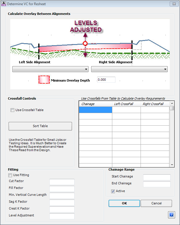
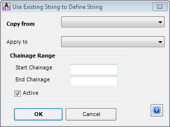
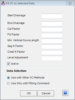
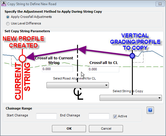
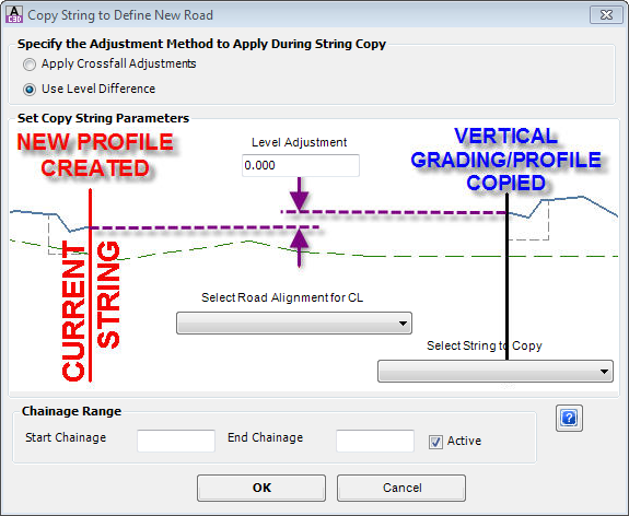
| | | This command provides access to a variety of methods to generate a vertical grading for the current ARD Object open in the Vertical Grading Editor.
| ||||||||||||||||||||||||||||||||||||||||||||||||||||||||||||||||||||||||||||||||||||||||||||||||||||||||||||||||||||||||||||||||||||||||||||||||||||||||||||||||||||||||||||||||||||||||||||||||||||||||||||||||||||||||||||||||||||||||||||||||||||||||||||||||||||||||||||||||||
| Output Tools | This collection of commands generate outputs in the drawing as well as create volume reports | |||||||||||||||||||||||||||||||||||||||||||||||||||||||||||||||||||||||||||||||||||||||||||||||||||||||||||||||||||||||||||||||||||||||||||||||||||||||||||||||||||||||||||||||||||||||||||||||||||||||||||||||||||||||||||||||||||||||||||||||||||||||||||||||||||||||||||||||||||
| | | Click to create an ARD Surface of the ARD Object being graded. This surface is outputted without regard to any other ARD Object (eg: Road intersections are ignored). The software applies the Surface Style assigned in the If the rebuild mode is set to Automatic in the settings, the surface automatically rebuilds as changes are applied through the Vertical Grading Editor. | ||||||||||||||||||||||||||||||||||||||||||||||||||||||||||||||||||||||||||||||||||||||||||||||||||||||||||||||||||||||||||||||||||||||||||||||||||||||||||||||||||||||||||||||||||||||||||||||||||||||||||||||||||||||||||||||||||||||||||||||||||||||||||||||||||||||||||||||||||
| | | Click to set the display options for the ARD Surface (as well as any other surfaces and model linework). The full details of this form are described in the | ||||||||||||||||||||||||||||||||||||||||||||||||||||||||||||||||||||||||||||||||||||||||||||||||||||||||||||||||||||||||||||||||||||||||||||||||||||||||||||||||||||||||||||||||||||||||||||||||||||||||||||||||||||||||||||||||||||||||||||||||||||||||||||||||||||||||||||||||||
| | | Click on this icon to generate a report of the volumes. | ||||||||||||||||||||||||||||||||||||||||||||||||||||||||||||||||||||||||||||||||||||||||||||||||||||||||||||||||||||||||||||||||||||||||||||||||||||||||||||||||||||||||||||||||||||||||||||||||||||||||||||||||||||||||||||||||||||||||||||||||||||||||||||||||||||||||||||||||||
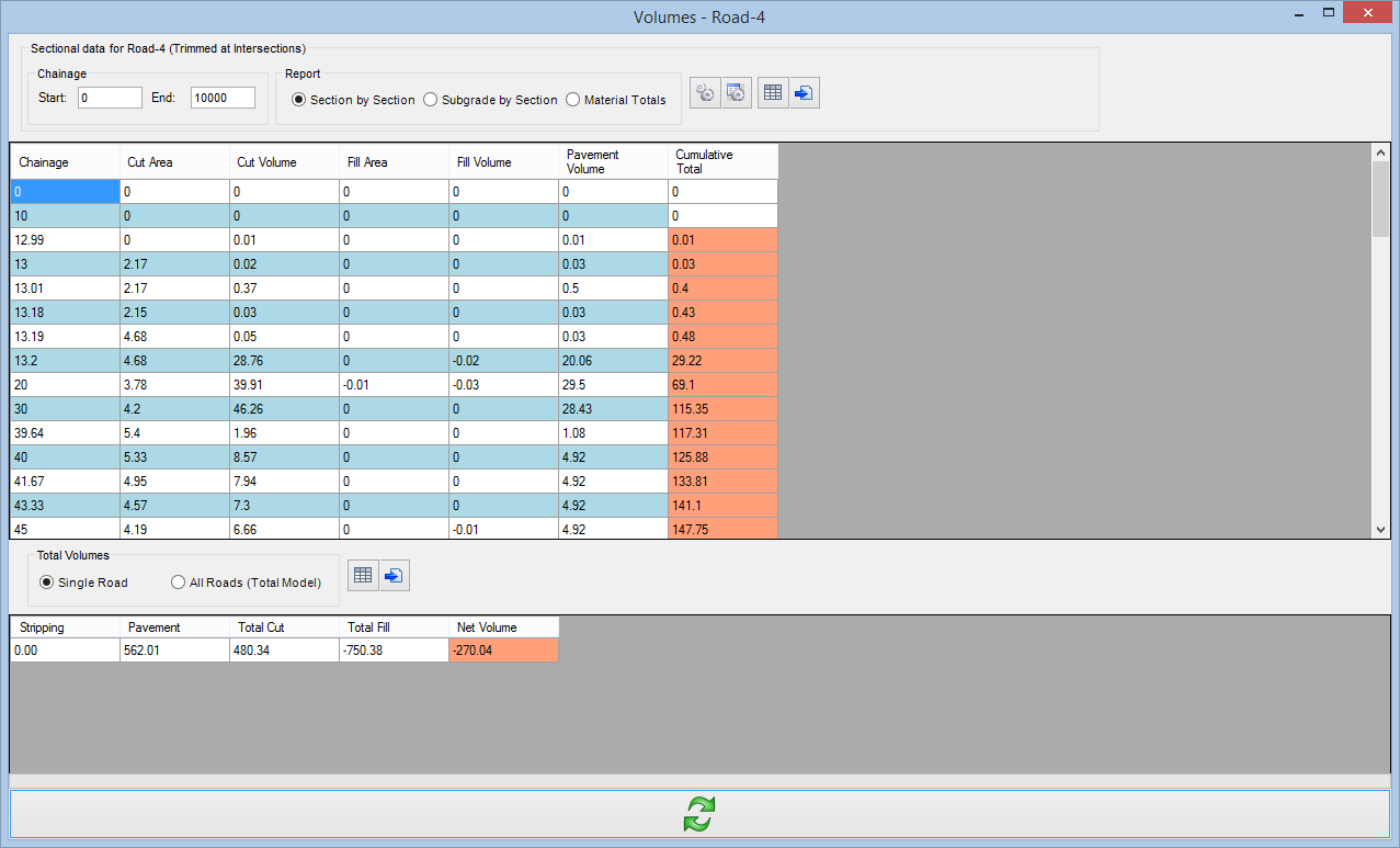 | ||||||||||||||||||||||||||||||||||||||||||||||||||||||||||||||||||||||||||||||||||||||||||||||||||||||||||||||||||||||||||||||||||||||||||||||||||||||||||||||||||||||||||||||||||||||||||||||||||||||||||||||||||||||||||||||||||||||||||||||||||||||||||||||||||||||||||||||||||||
| The details of this form can be found in the | ||||||||||||||||||||||||||||||||||||||||||||||||||||||||||||||||||||||||||||||||||||||||||||||||||||||||||||||||||||||||||||||||||||||||||||||||||||||||||||||||||||||||||||||||||||||||||||||||||||||||||||||||||||||||||||||||||||||||||||||||||||||||||||||||||||||||||||||||||||
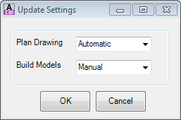
| | | Sets the status of automatic rebuild for linework and modelling. User inputs
| ||||||||||||||||||||||||||||||||||||||||||||||||||||||||||||||||||||||||||||||||||||||||||||||||||||||||||||||||||||||||||||||||||||||||||||||||||||||||||||||||||||||||||||||||||||||||||||||||||||||||||||||||||||||||||||||||||||||||||||||||||||||||||||||||||||||||||||||||||
| Update Tools | This collection of commands ensures the vertical grading is completely updated and enables undo/redo | |||||||||||||||||||||||||||||||||||||||||||||||||||||||||||||||||||||||||||||||||||||||||||||||||||||||||||||||||||||||||||||||||||||||||||||||||||||||||||||||||||||||||||||||||||||||||||||||||||||||||||||||||||||||||||||||||||||||||||||||||||||||||||||||||||||||||||||||||||
| | Undo edits in the current section | |||||||||||||||||||||||||||||||||||||||||||||||||||||||||||||||||||||||||||||||||||||||||||||||||||||||||||||||||||||||||||||||||||||||||||||||||||||||||||||||||||||||||||||||||||||||||||||||||||||||||||||||||||||||||||||||||||||||||||||||||||||||||||||||||||||||||||||||||||
| | | Redo edits in the current session | ||||||||||||||||||||||||||||||||||||||||||||||||||||||||||||||||||||||||||||||||||||||||||||||||||||||||||||||||||||||||||||||||||||||||||||||||||||||||||||||||||||||||||||||||||||||||||||||||||||||||||||||||||||||||||||||||||||||||||||||||||||||||||||||||||||||||||||||||||
| | Refreshes the display on screen - this command should not be required as most/all commands automatically result in an immediate update | |||||||||||||||||||||||||||||||||||||||||||||||||||||||||||||||||||||||||||||||||||||||||||||||||||||||||||||||||||||||||||||||||||||||||||||||||||||||||||||||||||||||||||||||||||||||||||||||||||||||||||||||||||||||||||||||||||||||||||||||||||||||||||||||||||||||||||||||||||
| | | Updates the intersection match in levels that affect the current Vertical Grading Design as well as updating all Models (linework and surfaces). | ||||||||||||||||||||||||||||||||||||||||||||||||||||||||||||||||||||||||||||||||||||||||||||||||||||||||||||||||||||||||||||||||||||||||||||||||||||||||||||||||||||||||||||||||||||||||||||||||||||||||||||||||||||||||||||||||||||||||||||||||||||||||||||||||||||||||||||||||||
| | | If screen flickering and unexpected repositioning of the IP during editing is experienced, it is recommend to turn the automatic rescaling off. Note: When Auto Rescale is off, the middle mouse button scroll does not operate as a zoom. | ||||||||||||||||||||||||||||||||||||||||||||||||||||||||||||||||||||||||||||||||||||||||||||||||||||||||||||||||||||||||||||||||||||||||||||||||||||||||||||||||||||||||||||||||||||||||||||||||||||||||||||||||||||||||||||||||||||||||||||||||||||||||||||||||||||||||||||||||||
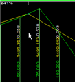
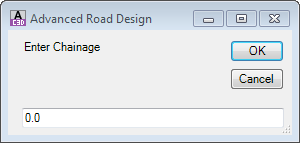
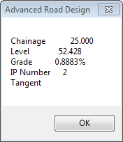
| | | This command is used to query the level at a particular chainage. Inputs are as follows:
| ||||||||||||||||||||||||||||||||||||||||||||||||||||||||||||||||||||||||||||||||||||||||||||||||||||||||||||||||||||||||||||||||||||||||||||||||||||||||||||||||||||||||||||||||||||||||||||||||||||||||||||||||||||||||||||||||||||||||||||||||||||||||||||||||||||||||||||||||||
| Navigation Tools | This collection of commands provide navigation of the grading window. Note: the middle mouse button is able to be used to zoom (scroll) and pan (hold) | |||||||||||||||||||||||||||||||||||||||||||||||||||||||||||||||||||||||||||||||||||||||||||||||||||||||||||||||||||||||||||||||||||||||||||||||||||||||||||||||||||||||||||||||||||||||||||||||||||||||||||||||||||||||||||||||||||||||||||||||||||||||||||||||||||||||||||||||||||
| | Zoom in by 25% | |||||||||||||||||||||||||||||||||||||||||||||||||||||||||||||||||||||||||||||||||||||||||||||||||||||||||||||||||||||||||||||||||||||||||||||||||||||||||||||||||||||||||||||||||||||||||||||||||||||||||||||||||||||||||||||||||||||||||||||||||||||||||||||||||||||||||||||||||||
| | | Zoom out by 25% | ||||||||||||||||||||||||||||||||||||||||||||||||||||||||||||||||||||||||||||||||||||||||||||||||||||||||||||||||||||||||||||||||||||||||||||||||||||||||||||||||||||||||||||||||||||||||||||||||||||||||||||||||||||||||||||||||||||||||||||||||||||||||||||||||||||||||||||||||||
| | Two button click pan. Click to select current location. Second click to move it to new location. | |||||||||||||||||||||||||||||||||||||||||||||||||||||||||||||||||||||||||||||||||||||||||||||||||||||||||||||||||||||||||||||||||||||||||||||||||||||||||||||||||||||||||||||||||||||||||||||||||||||||||||||||||||||||||||||||||||||||||||||||||||||||||||||||||||||||||||||||||||
| | | Click to zoom to display the entire string on screen | ||||||||||||||||||||||||||||||||||||||||||||||||||||||||||||||||||||||||||||||||||||||||||||||||||||||||||||||||||||||||||||||||||||||||||||||||||||||||||||||||||||||||||||||||||||||||||||||||||||||||||||||||||||||||||||||||||||||||||||||||||||||||||||||||||||||||||||||||||
| | Zoom to a window. Click and move the curser to make a 'window' selection and click again to zoom into that window | |||||||||||||||||||||||||||||||||||||||||||||||||||||||||||||||||||||||||||||||||||||||||||||||||||||||||||||||||||||||||||||||||||||||||||||||||||||||||||||||||||||||||||||||||||||||||||||||||||||||||||||||||||||||||||||||||||||||||||||||||||||||||||||||||||||||||||||||||||
| | | Click to pan window to desired region | ||||||||||||||||||||||||||||||||||||||||||||||||||||||||||||||||||||||||||||||||||||||||||||||||||||||||||||||||||||||||||||||||||||||||||||||||||||||||||||||||||||||||||||||||||||||||||||||||||||||||||||||||||||||||||||||||||||||||||||||||||||||||||||||||||||||||||||||||||
| | | Zooms to the Road alignment extents in the drawing | ||||||||||||||||||||||||||||||||||||||||||||||||||||||||||||||||||||||||||||||||||||||||||||||||||||||||||||||||||||||||||||||||||||||||||||||||||||||||||||||||||||||||||||||||||||||||||||||||||||||||||||||||||||||||||||||||||||||||||||||||||||||||||||||||||||||||||||||||||
| | | Click on this button to select a pipe in the VGE and zoom to that pipe in the drawing. | ||||||||||||||||||||||||||||||||||||||||||||||||||||||||||||||||||||||||||||||||||||||||||||||||||||||||||||||||||||||||||||||||||||||||||||||||||||||||||||||||||||||||||||||||||||||||||||||||||||||||||||||||||||||||||||||||||||||||||||||||||||||||||||||||||||||||||||||||||
| | IP, Ch and RL | Displays the IP number (1 on left incrementing to the right), chainage and RL of IP closest to mouse position | ||||||||||||||||||||||||||||||||||||||||||||||||||||||||||||||||||||||||||||||||||||||||||||||||||||||||||||||||||||||||||||||||||||||||||||||||||||||||||||||||||||||||||||||||||||||||||||||||||||||||||||||||||||||||||||||||||||||||||||||||||||||||||||||||||||||||||||||||||
| | | Sets the item to snap to when using the | ||||||||||||||||||||||||||||||||||||||||||||||||||||||||||||||||||||||||||||||||||||||||||||||||||||||||||||||||||||||||||||||||||||||||||||||||||||||||||||||||||||||||||||||||||||||||||||||||||||||||||||||||||||||||||||||||||||||||||||||||||||||||||||||||||||||||||||||||||
| | | Sets the maximum scale exaggeration of the longsection | ||||||||||||||||||||||||||||||||||||||||||||||||||||||||||||||||||||||||||||||||||||||||||||||||||||||||||||||||||||||||||||||||||||||||||||||||||||||||||||||||||||||||||||||||||||||||||||||||||||||||||||||||||||||||||||||||||||||||||||||||||||||||||||||||||||||||||||||||||
| | Ch, Level | Displays the chainage and level of the mouse position in the VGE window. | ||||||||||||||||||||||||||||||||||||||||||||||||||||||||||||||||||||||||||||||||||||||||||||||||||||||||||||||||||||||||||||||||||||||||||||||||||||||||||||||||||||||||||||||||||||||||||||||||||||||||||||||||||||||||||||||||||||||||||||||||||||||||||||||||||||||||||||||||||
| | | Apply and exit the Vertical Grading Editor. | ||||||||||||||||||||||||||||||||||||||||||||||||||||||||||||||||||||||||||||||||||||||||||||||||||||||||||||||||||||||||||||||||||||||||||||||||||||||||||||||||||||||||||||||||||||||||||||||||||||||||||||||||||||||||||||||||||||||||||||||||||||||||||||||||||||||||||||||||||
| | | Exit the Vertical Grading Editor. Edits made are saved while the editor is open. Use the Undo command to undo any changes. | ||||||||||||||||||||||||||||||||||||||||||||||||||||||||||||||||||||||||||||||||||||||||||||||||||||||||||||||||||||||||||||||||||||||||||||||||||||||||||||||||||||||||||||||||||||||||||||||||||||||||||||||||||||||||||||||||||||||||||||||||||||||||||||||||||||||||||||||||||
| | Command Prompt | Describes the command details and gives instruction on executing a command in the VGE. | ||||||||||||||||||||||||||||||||||||||||||||||||||||||||||||||||||||||||||||||||||||||||||||||||||||||||||||||||||||||||||||||||||||||||||||||||||||||||||||||||||||||||||||||||||||||||||||||||||||||||||||||||||||||||||||||||||||||||||||||||||||||||||||||||||||||||||||||||||
| | | Saves the current design | ||||||||||||||||||||||||||||||||||||||||||||||||||||||||||||||||||||||||||||||||||||||||||||||||||||||||||||||||||||||||||||||||||||||||||||||||||||||||||||||||||||||||||||||||||||||||||||||||||||||||||||||||||||||||||||||||||||||||||||||||||||||||||||||||||||||||||||||||||
| | | Removes all IP's except for the end points | ||||||||||||||||||||||||||||||||||||||||||||||||||||||||||||||||||||||||||||||||||||||||||||||||||||||||||||||||||||||||||||||||||||||||||||||||||||||||||||||||||||||||||||||||||||||||||||||||||||||||||||||||||||||||||||||||||||||||||||||||||||||||||||||||||||||||||||||||||
| | | |||||||||||||||||||||||||||||||||||||||||||||||||||||||||||||||||||||||||||||||||||||||||||||||||||||||||||||||||||||||||||||||||||||||||||||||||||||||||||||||||||||||||||||||||||||||||||||||||||||||||||||||||||||||||||||||||||||||||||||||||||||||||||||||||||||||||||||||||||
| |  Open Template Editor Open Template Editor | Select this button to create/edit a typical cross section template. Full details in the Create/Edit Section Template form. | ||||||||||||||||||||||||||||||||||||||||||||||||||||||||||||||||||||||||||||||||||||||||||||||||||||||||||||||||||||||||||||||||||||||||||||||||||||||||||||||||||||||||||||||||||||||||||||||||||||||||||||||||||||||||||||||||||||||||||||||||||||||||||||||||||||||||||||||||||
| |  Open Design Data Form Open Design Data Form | Select this button to access the Design Data Form. | ||||||||||||||||||||||||||||||||||||||||||||||||||||||||||||||||||||||||||||||||||||||||||||||||||||||||||||||||||||||||||||||||||||||||||||||||||||||||||||||||||||||||||||||||||||||||||||||||||||||||||||||||||||||||||||||||||||||||||||||||||||||||||||||||||||||||||||||||||
| | | Select this button to open an instance of the Cross Section Viewer. The designer will be prompted to select a cross section to initially load into the viewer. | ||||||||||||||||||||||||||||||||||||||||||||||||||||||||||||||||||||||||||||||||||||||||||||||||||||||||||||||||||||||||||||||||||||||||||||||||||||||||||||||||||||||||||||||||||||||||||||||||||||||||||||||||||||||||||||||||||||||||||||||||||||||||||||||||||||||||||||||||||
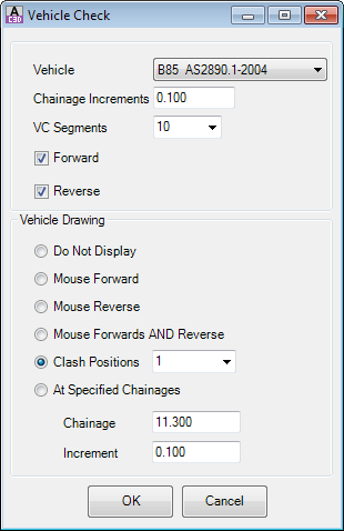
| | | Click on this option to check vehicle clearance along a driveway alignment.
| ||||||||||||||||||||||||||||||||||||||||||||||||||||||||||||||||||||||||||||||||||||||||||||||||||||||||||||||||||||||||||||||||||||||||||||||||||||||||||||||||||||||||||||||||||||||||||||||||||||||||||||||||||||||||||||||||||||||||||||||||||||||||||||||||||||||||||||||||||
| | | Toggles display depending on Vehicle Drawing options selected. | ||||||||||||||||||||||||||||||||||||||||||||||||||||||||||||||||||||||||||||||||||||||||||||||||||||||||||||||||||||||||||||||||||||||||||||||||||||||||||||||||||||||||||||||||||||||||||||||||||||||||||||||||||||||||||||||||||||||||||||||||||||||||||||||||||||||||||||||||||
| | | Rebuilds the model and redraws the linework - only shows if the Model/Linework udpating is set to Manual. | ||||||||||||||||||||||||||||||||||||||||||||||||||||||||||||||||||||||||||||||||||||||||||||||||||||||||||||||||||||||||||||||||||||||||||||||||||||||||||||||||||||||||||||||||||||||||||||||||||||||||||||||||||||||||||||||||||||||||||||||||||||||||||||||||||||||||||||||||||
| | | Rebuilds the surface - only shows if Surface updating is set to Manual. | ||||||||||||||||||||||||||||||||||||||||||||||||||||||||||||||||||||||||||||||||||||||||||||||||||||||||||||||||||||||||||||||||||||||||||||||||||||||||||||||||||||||||||||||||||||||||||||||||||||||||||||||||||||||||||||||||||||||||||||||||||||||||||||||||||||||||||||||||||
| | | Click on this button to zoom to the extents of all open cross section locations. Before clicking After Clicking | ||||||||||||||||||||||||||||||||||||||||||||||||||||||||||||||||||||||||||||||||||||||||||||||||||||||||||||||||||||||||||||||||||||||||||||||||||||||||||||||||||||||||||||||||||||||||||||||||||||||||||||||||||||||||||||||||||||||||||||||||||||||||||||||||||||||||||||||||||
| | | Click on this button to add extra sampling (chainages) to the string. Full details in the Add Extra Sections form. | ||||||||||||||||||||||||||||||||||||||||||||||||||||||||||||||||||||||||||||||||||||||||||||||||||||||||||||||||||||||||||||||||||||||||||||||||||||||||||||||||||||||||||||||||||||||||||||||||||||||||||||||||||||||||||||||||||||||||||||||||||||||||||||||||||||||||||||||||||
| | | Tick on = auto update - editing the vertical grading automatically updates all other dependent strings and models. Tick off = manual - editing the vertical grading will only update the cross section window displayed. Will update linework and models and other strings upon exit. | ||||||||||||||||||||||||||||||||||||||||||||||||||||||||||||||||||||||||||||||||||||||||||||||||||||||||||||||||||||||||||||||||||||||||||||||||||||||||||||||||||||||||||||||||||||||||||||||||||||||||||||||||||||||||||||||||||||||||||||||||||||||||||||||||||||||||||||||||||
Back To Top
kennedydelonost1959.blogspot.com
Source: https://www.help.civilsurveysolutions.com/OnlineHelp/CSD_Siteworks/Commands/VGE-VerticalGradingEditor/VGE-VerticalGradingEditor.htm




0 Response to "Draw Vetical Crest Curve Given Slopes in Autocad"
إرسال تعليق